Industrial UPS
Industrial UPS
- On-line double conversation topology
- Customized products based on specification
- Independent modules (Rectifier, Inverter and optional Stabilizer on bypass) sized individually
- Option of operation with multi front panels to give full control on the system to operator
- Galvanically isolated output (inverter transformer is standard, rectifier and bypass transformers are optional) for maximum safety on critical loads
- SCR Rectifier to ensure reliable operation in rugged mains conditions
- IGBT (PWM) controlled inverter with high frequency switching to ensure no waveform distortion for reactive and nonlinear loads.
- Compatible with Lead Acid ( vented/sealed) and NiCd (vented/gas recombination) batteries
- Communication (Free alarm contacts, remote PC monitoring, Modbus, SNMP, Profibus, DNP 3.0 via RS 232, RS 485, USB or Ethernet TCP/IP ports)
General
Model
KGK Series
Topology
Double Conversion Online System with Output Isolation Transformer
Control
Microprocessor Controlled System
Rectifier
Topology
Full Bridge Phase Angle Controlled Thyristor Module Rectifier
Control
Microprocessor Controlled System
Isolation Transformer (OPTIONAL)
Galvanically Isolated
Nominal Input Voltage
110 VAC / 220 VAC / 230 VAC / 240 VAC / 380 VAC / 400 VAC / 415 VAC / 480 VAC ±15%
Nominal Input Frequency
50 hz. ±5% or 60 hz. ±5%
Input Cosφ
≥ 0.8 Inductive (6 Pulse) ≥ 0.85 Inductive (12 Pulse) ≥ 0.95 Inductive (12 Pulse with active harmonic elimination)
Total harmonic Distortion (THDi)
≤ 30% (6 Pulse), ≤ 10% (12 Pulse), ≤ 5% (12 Pulse with active harmonic elimination)
Nominal DC Voltage
110 VDC / 125 VDC / 144 VDC / 220 VDC / 264 VDC / 360 VDC
Battery Charging Principle
Constant Current / Constant Voltage
Float Charge Voltage (V/Cell)
2,4 Lead Acid Battery 1,60 NiCd Battery (Based on battery brand and type)
Boost Charge Voltage (V/Cell)
2.23 Lead Acid Battery 1,40 NiCd Battery Based (Based on battery brand and type)
Protections
Input: Thermic-Magnetic Over Current Protection, Over Voltage Protection, Phase Sequence Free Operation (3 Phase), Soft Start, MCB Output: Short Circuit Protection, Over Voltage Protection Battery: L-C filters, Overcurrent and Over Voltage Protection
Measurements
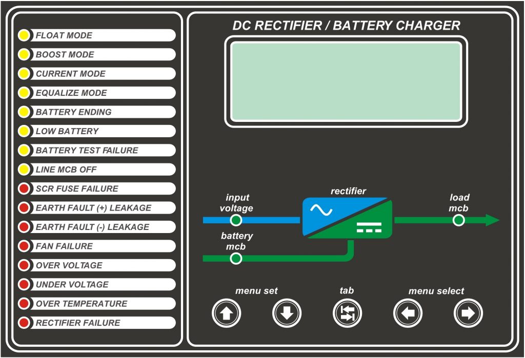
LCD Display for Line Voltage / Frequency / Current (Standard in 1 Phase, Optional for 3 Phase), Battery Output Voltage / Current, Load Output Voltage, Charger Total Output Current
Indicators
Float Mode, Boost Mode, Current Mode, Equalize Mode, Battery Ending, Low Battery, Battery Test Failure, Line Failure, Fan Failure, Over Voltage, Under Voltage, Over Temperature, Rectifier Failure, SCR Fuse Failure, Mains Available, Load MCB, Battery MCB
Adjustable Parameters
Float Charge Voltage, Boost Charge Voltage, Equalize Charge Voltage, Battery Charge Current, Rectifier Total Output Current, Low Battery Voltage Alarm, Earth Fault Leakage Current Alarm (only available in 4 line LCD), Battery Ending Voltage Alarm, Online Battery Test Parameters, Auto Boost Charge Parameters, Password
Event History
Events recorded and displayed on front panel and on PC via remote communication
Open or closed free alarm contacts
Low Battery, Mains Input Normal / Failure, Charger Failure, Overtemperature, Charger Overvoltage, Load MCB ON/ OFF, Battery MCB ON / OFF, Earth Fault
Sound Alarm
On Warning Messages 2 Short ‘beep’ per 2 seconds
Control Elements
Battery Test
Automatic or manual selectable. Please refer to user manual for details
Boost Timer
0 – 99,9 hours adjustable by 1 minute accuracy
Current Limitation
Total output current and battery current can be adjusted separately
Inverter
Topology
3 Full Bridge 6 high Frequency IGBT Inverter Modules (3 Phase); 1 Full Bridge 2 high Frequency IGBT Inverter Modules (1 Phase)
Isolation Transformer
Galvanically Isolated (standard)
Power Factor
0.8
Nominal Input Voltage
110 VDC / 125 VDC / 144 VDC / 220 VDC / 264 VDC / 360 VDC
Nominal Output Voltage
110 VAC / 220 VAC / 230 VAC / 240 VAC / 380 VAC / 400 VAC / 415 VAC / 480 VAC
Output Voltage Ripple RMS
≤ 1% RMS AC of Output Voltage
Voltage Tolerance
Static
± 1%
Dynamic with 100% load change
± 10% in 50 msec.
Overload
Between 100% – 125%
10 min.
Between %125 – 150%
1 min.
Between %150 – 300%
1 sec.
Waveform
Pure Sinusoidal
Total harmonic Distortion (ThDv)
at Linear Load
< 3%
at Non-Linear Load
< 7%
Crest Factor
3 : 1 (1 second)
Total harmonic Distortion (ThDv)
While synchronized with the line
50 Hz / 60 Hz ±2%
While not synchronized with the line
50 Hz / 60 Hz ± 0.1%
Switching Frequency
16 Khz.
Short-circuit behaviour:
3 x Nominal Output Current
Protection
Short Circuit Protection, Over Voltage Protection, Under Voltage Protection, Over Current Protection and Over Temperature Protection
Front Panel Indicatiors
Inverter not Synchronized, Inverter DC Input High/Low, Bypass Out of Limit, Battery Fuse OFF, Bypass MCB OFF, DC Input MCB OFF, Inverter Overload, Internal Overtemperature, Inverter Failure, IGBT SCR Fuse Failure, Bypass Overtemperature Failure, Inverter Output High / Low, Inverter Overtemperature
Front Panel Set Menu
UPS Mode (UPS, ECO, Bypass Inhibit), DC Cut off, Low Battery Level, Output Voltage Adjustment, Set Output Frequency, Auto Start ON/OFF, Date, Alarm Sound ON/OFF, Password
Alarm Contacts (1 Open 1 Closed)
Inverter Failure, Overtemperature, Load on Bypass / Inverter, Inverter not Synchronized, DC Input Low /High, Battery Fuse OFF, Bypass out of Limit, Inverter Overload
Communication (OPTIONAL)
RS 485 / RS 232 / Ethernet Ports, Remote PC Control, Modbus, Profibus, SNMP, DNP 3.0 Protocols and TCP/IP options
Paralleling (OPTIONAL)
Parallel Redundancy
Static By-Pass
Topology
Uninterruptible static switch with back-feed protection
Bypass System
No break semiconductor thyristor – thyristor
Isolation Transformer (OPTIONAL)
Galvanically Isolated
Nominal Frequency
50/60 Hz ± 2%
Inverter/Bypass transfer time
Inverter failure
Max. 5 msec.
Overload or manual transfer
0 msec.
Bypass/Inverter transfer time
0 msec.
Efficiency
>99%
Mechanical By-Pass
Topology
Make before break mechanical switch with locking system (OPTIONAL:External By-Pass Switch)
Safety & Environment
Over Voltage Protection
IEEE 587 4500 A, 110 Joules (standard) / 40kA Surge Arrestor (OPTIONAL)
Electrical Interference Reduction
FCC Part 15 Class B
Electrical Standards
IEC 62040-3 (Performance), EN 50091-1 (Security) / EN 50091-2 (EMC)
Protection Level / Color
IP 20 / RAL 7035 (Standard), (Higher IP rating and different colors are available, please consult)
MTBF
100,000 hrs. (w/out battery group)
Enclosure Material
Mild Steel, Zinc-phosphate coated; 100 µm electrostatic paint; 1.5 mm thickness
Cooling
Forced Fan (Standard) / Natural (OPTIONAL)
Cable Entry
Bottom (Standard) / Top (OPTIONAL)
Heater & Lightning
OPTIONAL
Distribution
OPTIONAL
Operating Temperature
-10 / +40 °C. (Higher operating temperatures are available, please consult)
Relative humidity
0 – 90%. Higher relative humidity are available, please consult
Operating Altitude
Max. 1000 Mt. (Higher altitudes requires de-rating, please consult )
Noise Level
Max. 60 db